So I’ve now had the solar panels up for a month now… and so far, we’ve had a run of very overcast or wet days.
Figures… and we thought this was the “sunshine state”?
I still haven’t done the automatic switching, so right now the mains power supply powers the relay that switches solar to mains. Thus the only time my cluster runs from solar is when either I switch off the mains power supply manually, or if there’s a power interruption.
The latter has not yet happened… mains electricity supply here is pretty good in this part of Brisbane, the only time I recall losing it for an extended period of time was back in 2008, and that was pretty exceptional circumstances that caused it.
That said, the political football of energy costs is being kicked around, and you can bet they’ll screw something up, even if for now we are better off this side of the Tweed river.
A few weeks back, with predictions of a sunny day, I tried switching off the mains PSU in the early morning and letting the system run off the solar. I don’t have any battery voltage logging or current logging as yet, but the system went fine during the day. That evening, I turned the mains back on… but the charger, a Redarc BCDC1225, seemingly didn’t get that memo. It merrily let both batteries drain out completely.
The IPMI BMCs complained bitterly about the sinking 12V rail at about 2AM when I was sound asleep. Luckily, I was due to get up at 4AM that day. When I tried checking a few things on the Internet, I first noticed I didn’t have a link to the Internet. Look up at the switch in my room and saw the link LED for the cluster was out.
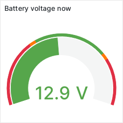
At that point, some choice words were quietly muttered, and I wandered downstairs with multimeter in hand to investigate. The batteries had been drained to 4.5V!!!
I immediately performed some load-shedding (ripped out all the nodes’ power leads) and power-cycled the mains PSU. That woke the charger up from its slumber, and after about 30 seconds, there was enough power to bring the two Ethernet switches in the rack online. I let the voltage rise a little more, then gradually started re-connecting power to the nodes, each one coming up as it was plugged in.
The virtual machine instances I had running outside OpenNebula came up just fine without any interaction from me, but it seems OpenNebula didn’t see it fit to re-start the VMs it was responsible for. Not sure if that is a misconfiguration, or if I need to look at an alternate solution.
Truth be told, I’m not a fan of libvirt either… overly complicated for starting QEMU VMs. I might DIY a solution here as there’s lots of things that QEMU can do which libvirt ignores or makes more difficult than it should be.
Anyway… since that fateful night, I have on two occasions run the cluster from solar without incident. On the off-chance though, I have an alternate charger which I might install at some point. The downside is it doesn’t boost the 12V input like the other one, so I’d be back to using that Xantrex charger to charge from mains power.
Already, I’m thinking about the criteria for selecting a power source. It would appear there are a few approaches I can take, I can either purely look at the voltages seen at the solar input and on the battery, or I can look at current flow.
Voltage wise, I tried measuring the solar panel output whilst running the cluster today. In broad daylight, I get 19V off the panels, and at dusk it’s about 16V.
Judging from that, having the solar “turn on” at 18V and “turn off” at 15V seems logical. Using the comparator approach, I’d need to set a reference of 16.5V and tweak the hysteresis to give me a ±3V swing.
However, this ignores how much energy is actually being produced from solar in relation to how much is being consumed. It is possible for a day to start off sunny, then for the weather to cloud over. Solar voltage in that case might be sitting at the 16V mentioned.
If the current is too low though, the cluster will drain more power out than is going in, and this will result in the exact conditions I had a few weeks ago: a flat battery bank. Thus I’m thinking of incorporating current shunts both on the “input” to the battery bank, and to the “output”. If output is greater than input, we need mains power.
There’s plenty of literature about interfacing to current shunts. I’ll have to do some research, but immediately I’m thinking an op-amp running from the battery configured as a non-inverting DC gain block with the inputs going to either side of the current shunt.
Combining the approaches is attractive. So turn on when solar exceeds 18V, turn off when battery output current exceeds battery input current. A dual op-amp, a dual comparator, two current shunts, a R-S flip-flop and a P-MOSFET for switching the relay, and no hysteresis calculations needed.


Recent Comments