solar

Solar Cluster: Power controller installed

Well, I finally got around to installing that power controller.

Yes, the top of that rack is getting to be a pigsty. Even the controller isn’t my best work:

You can see above I’ve just tacked wires onto the points I need and brought those out to a terminal strip.  There’s provision there for some PWM-controlled fans, but right now this is unused.  I’ve omitted the parts not required for the application.  If this works out, I might consider doing another board, this time better dedicated to the task at hand.

With that controller in place, I’ve now wound the charger back up.  In fact I made a whoopsie at first: I forgot that the Vout pot on the HEF-600C-12 sets the float voltage and wound that right up to 14.4V which meant a boost voltage of 15V!

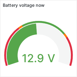
Thankfully I looked over at the volt meter on the solar controller and realised my mistake quick.  15 seconds won’t hurt anything, but it is now set at 13.6V.  You don’t even see it on the 40-sample average.  The controller should let the mains charger sit there for an hour before it reconsiders the need for mains.

I think my next step … there’s a yard that could do with a hair cut… I’ll drag the mower out and chase that around the yard for a bit.  Then we’ll see what it looks like.


Okay, back from a little mowing… and sure enough, the controller is mostly doing the right thing.  I think I’ll need to tweak some set-points, maybe set the solar threshold lower.  Thankfully the “inhibit” LED is just an indication that it considers the solar voltage low, the solar is going to be on no matter what.

Yes, that SSR is massive for the job. It’s what I had on hand at the time. I’ll probably replace it with something small, maybe a reed relay since they’re cheap.

Right at this point, I have the SSR’s inputs connected between the solar V+ and the BC-547B on the board, so when the sun *does* go down, the mains power will be turned back on no matter what the controller thinks.

A close-up look of the status LEDs shows what mode we’re in:

We’ll ignore the temperature ones. Ultimately they indicate the state of the fan controller, and in this state, it’d be running the fans, as indicated by the Fan PWM LED to the left. Temperature is measured by the sensor in the ATTiny24A on-board, so not highly accurate.

The other mystery “LED” is the shiny surface on the BC-547B to the left of the two source status LEDs.

Here, I suspect the sun ducked behind a cloud so the voltage dropped, hence both “inhibit” LEDs came on. Earlier, “Float” was lit (you can sort-of make it out in the previous photo), the charger was actually actively trying to charge the battery, but to the controller it looked to be done. It left it go for the hour as programmed, then turned off the mains charger to let the solar panel take over.

The idea is that during the day, if it gets low, give it a boost from mains, then go back to solar. We only want to rely on mains at night.

Now, it should stay in that state until tonight, when the lack of sun should bring the mains charger online (by sheer fact that the solar panels power the “coil” of the relay).


So, I saw that, and had a look… sure enough, the controller is still asserting that the mains charger should be off. I think I need to bump the battery thresholds up a bit, although that’s still safely above the danger zone, it’s lower than I’m comfortable with.

Right up until 5:58PM, it seems the MCU just held on, thinking the battery voltage was “good enough”, so no need for a charge yet. I might want to drop the solar threshold down some so it doesn’t “flap” when broken cloud passes over, then raise the minimum battery threshold a bit.

Even now, the thing that’s turning the mains charger on is the fact that the 1.5V coming off the panels is not sufficient for activating the solid-state relay I’m using. I’m thankful I wired the SSR to Vsolar and made the MCU output open-collector. This is a useful little safety feature, making it impossible for the MCU to latch-up and hold the mains charger off, as the sun will eventually set, and that will force the mains charger to turn on like it did tonight.

Solar Cluster: Return of the power controller

Well, I’ve been tossing up how to control the mains charger for a while now.

When I first started the project, my thinking was to use an old Xantrex charger we had kicking around, and just electrically disconnect it from the batteries when we wanted to use the solar power.  I designed a 4-layer PCB which sported a ATTiny24A microcontroller, MOSFETs (which I messed up) and some LEDs.

This was going to be a combined fan controller and power management unit.  It had the ability (theoretically) to choose a supply based on the input voltage, and to switch if needed between supplies.

It didn’t work out, the charger got really confused by the behaviour of the controller.  I was looking to re-instate it using the Redarc solar controller, but I never got there.  In the end, it was found that the Redarc controller had problems switching sources and would do nothing whilst the batteries went flat.

We’ve now replaced both ends of the system.  The solar controller is a Powertech MP3735 and integrates over-discharge protection.  The mains charger is now a MeanWell HEP-600C-12 (which has not missed a beat since the day it was put in).

Unlike my earlier set-up, this actually has a 5V logic signal to disable it, and my earlier controller could theoretically generate that directly.

Looking at the PCB of my earlier power controller attempt, it looks like this could still work.

Above is the PCB artwork.  I’ve coloured in the sections and faded out the parts I can omit.

In green up the top-left we have the mains control/monitoring circuitry.  We no longer see the mains voltage, so no point in monitoring it, so we can drop the resistor divider that fed the ADC.  This also means we no longer need the input socket P2.

Q2 and Q7 were the footprints of the two P-channel MOSFETs.  We don’t need the MOSFETs themselves, but the signals we need can be found on pin 1 of Q2.  This is actually the open-drain output of Q1, which we may be able to hook directly to the REMOTE+ pin on the charger.  A pull-up between there and the charger’s 5V rail, and we should be in business.

In yellow, bottom left is the solar monitoring interface.  This is still useful, but we won’t be connecting solar to the battery ourselves, so we just keep the monitoring parts.  The LED can stay as an indicator to show when solar is “good enough”.

In purple, occupying most of the board, is the controller itself.  It stays for obvious reasons.

In red, is the fan control circuitry.  No reason why this can’t stay.

In blue is the circuitry for monitoring the battery voltage.  Again, this stays.

The main advantage of doing this is I already have the boards, and a number of microcontrollers already present.  There’s a board with all except the big MOSFETs populated: with the MOSFETs replaced by 3-pin KK sockets.

How would the logic work?  Much the same as the analogue version I was pondering.

  • If battery voltage is low, OR, the sun has set, enable the mains charger.

What concerned me about an analogue solution was what would happen once the charger got to the constant-voltage stage.  We want to give it a bit of time to keep the battery topped up.  Thus it makes sense to shut down the charger after a fixed delay.

This is easy to do in a microcontroller.  Not hard with analogue electronics either, it’s fundamentally just a one-shot, but doing it with an MCU is a single-chip solution.  I can make the delay as long as I like.  So likely once the battery is “up to voltage”, I can let it float there for an hour, or until sunrise if it’s at night.

Solar Cluster: Measuring the battery voltage

So, I was just updating the project details for this project, and I happened to see this blog post about reading the DC voltage input on the TS-7670v2.

I haven’t yet gotten around to finishing the power meters that I was building which would otherwise be reading these values directly, but they were basically going to connect via Modbus to the TS-7670v2 anyway.  One of its roles, aside from routing between the physical management network (IPMI and switch console access), was to monitor the battery.

I will have to explore this.  Collectd doesn’t have a general-purpose I²C module, but it does have one for barometer modules, so with a bit of work, I could make one to measure the voltage input which would tell me what the battery is doing.

Solar Cluster: Next steps, better control of the charger

So, a few weeks ago I installed a new battery charger, and tweaked it so that the solar did most of the leg work during the day, and the charger kept the batteries topped up at night.

I also discussed the addition of a new industrial PC to perform routing and system monitoring functions… which was to run Gentoo Linux/musl. For now, that little PC is still running Debian Stretch, but for 45 days, it was rock solid. The addition of this box, and taking on the role of router to the management network meant I could finally achieve one of my long-term goals for the project: decommissioning the old server.

The old server is still set up with all my data and software… but now the back-up cron job calls /sbin/poweroff when it’s done, and the BIOS is set to wake the machine up in the evening ready to receive a back-up late at night.

In its place, a virtual machine clone of the box, handles my email and all the old functions of that server. This was all done just prior to my father and I leaving for a 3 week holiday in the Snowy Mountains.

I did have a couple of hiccups with Ceph OSDs crashing … but basically re-starting the daemons (done remotely whilst travelling through Cowra) got everything back up. A bit of placement group cleaning, and everything was back online again. I had another similar hiccup coming out of Maitland, but once again, re-starting the daemons fixed it. No idea why it crashed, that’s something I’ll have to investigate.

Other than that, the cluster itself has run well.

One thing that did momentarily kill the industrial PC though: I wandered down to the rack with a small bus-powered 2.5″ HDD with the intent of re-starting my Gentoo builds. This HDD had the same content as the 3.5″ HDD I had plugged in before. I figured being bus powered, I would not be dependent on mains, and it could just chug away to its heart’s content.

No such luck, the moment I plugged that drive in, the little machine took great umbrage to the spinning rust now vacuuming the electrons away from its core functions, and shut down abruptly. I’ve now brought my 3.5″ drive and dock down, plugged that into the wall, and have my builds resuming. If power goes off, hopefully the machine either handles the loss of swap gracefully. If it does crash, the watchdog will take care of it.

Thus, I have the little TS-7670 first attempting a build of gcc, to see how we go. Finger’s crossed our power should remain up. There was at least one outage in the time we were away, but hopefully we should get though this next build!

The next step I think should be to add some control of the mains charger to allow the batteries to be boosted to full charge overnight. The thinking is a simple diode-OR arrangement. Many comparators such as the LM393 have an open-collector output, which gives us this for free.

The theory is this.

The battery bank powers a simple circuit which runs of a 5V regulator. That regulator powers a dual comparator IC and provides a reference voltage. The comparator draws bugger all power, so I’m happy to use a linear PSU here. It’s mainly there as a voltage reference.

Precision isn’t really the aim here, so adjustable pots will make life easier.

The voltages from the battery bank and the solar panel are fed through voltage dividers to bring the voltages down to below 5V, then those voltages are individually fed into separate pots that control the hysteresis. I can adjust all points of the system.

The idea is that should the batteries get too low, or the sun go down, one or the other (or both) comparators will go low and pull down on R2. If the batteries are high and the sun is up, nothing pulls on R2 so the REMOTE+ pin on the HEP-600C-12 is allowed to float to +5V, turning off the mains charger.

The advantage of this is there’s no programming of a microcontroller, it’s just analogue electronics. The LM393s are pretty hardy things, the datasheet says they’ll run at 36V and can accept a maximum voltage of VCC-1.5V; so if I run at 5V, 3.5V is my recommended maximum. The adjustment pots should let me set a threshold voltage that avoids going above this.

I mainly need 5V for the HEP-600C-12, and for providing that stable known voltage reference. The LM78C05 should be fine for this.

Once I’ve done that, I should be able to wind that charger back up to its factory setting of 14.4V, which will mean that overnight the batteries will be charged back to full charge.

Solar Cluster: Fine Tuning

So yesterday I wound back the mains charger so that the solar would take on the load during the day.  Seems I wound it back a bit far, and the mains charger did almost no work overnight, leaving the battery somewhere around 11.8V.

That’s a wee bit low for my comfort.  Yes, they are deep cycle AGMs, but I’d rather not get that low.

Thus, I wound it up a bit, float at 12.8V, so Vboost at 13.6V.  That looks to be the sweet spot.  Now that the sun is up, I’m getting nice healthy amps of current down the wire from the roof:

The cluster is drawing about 8A, so that’s the cluster powered, and about 6A going to the batteries. It intermittently peaks about 15A or so.

I also found myself fine tuning the Ethernet settings on the border router. For some reason, its Realtek RTL8139 was happy to talk to the Cisco SG-200-08 it was connected to before, but didn’t quite get along with the Linksys LGS326-AU. I’ve told the switch to force 100Mbps full-duplex MDIX (evidently, it’s a cross-over cable), and so far, that seems to have settled things down.

Solar Cluster: ADSL powered by the sun

So, I’ve now moved the ADSL and router onto the battery supply. This has added an extra amp of load, but really, the solar panel handles this easy.

I dug up one of my spare switchmode PSU modules and then got to thinking about how I’d mount the thing. In the end, double sided tape… to keep the terminals of the adjustment pot from shorting, to a piece of old copper clad PCB from the project graveyard, with some wires soldered on.

The donor PCB already had regions cut out for terminals around the edge, so I could use those for drilling mounting holes. I just made additional terminal pads for soldering the input and output supply rails. Initially I tried putting a 1mF capacitor across the output, but evidently the one I grabbed was crook as it presented a 10Ω load. I don’t think the cause was due to it charging. The PSU has a 220µF there already, so let’s see how it fares.

Fairly simple, +12V comes in via the orange wire into IN+, the “LM2596” steps that down to 5V, comes out the red wire. Screw terminals allow me to swap input and output.

Before hooking it up to the ADSL modem, I made sure to dial it in to 5V.

Meh… who’s going to care about 3mV. 🙂

As it happens, the original PSU puts out 5.3V. I think I’m closer. I can always dial it up if needed.

I put the lid on the case and made up the rest of my wiring harness. One 5A blade fuse, a bit of work around the back of the rack, and it was installed.

In the meantime, I have my old server busy pushing its last daily back-up across to a newly provisioned virtual machine on the cluster.

One problem this presents is that this one VM occupies about 70% of my usable storage cluster capacity. The cases can take one 2.5″ HDD, which unless you’re willing to risk it with Seagate (I’ve had too many of them fail), top-out at 2TB.

There are SSDs too, but I’m not made of money, and I’ve already spent the cost of a small car on this cluster as it is. My thinking is I might look at modifying the cases with a new lid to accept a 3.5″ HDD. If I make the case a wee bit taller, a 3.5″ HDD would fit in the lid, and I could add fans around it to cool it.

The other option is to make external eSATA 3.5″ DIN-rail mounted cases. I did look online, but didn’t see any for sale. That said, space is getting squeezy on that DIN rail, and I do have to be mindful of cooling.

Solar Cluster: Beware, I’m ARMed

Last night, I got home, having made a detour on my way into work past Jaycar Wooloongabba to replace the faulty PSU.
It was a pretty open-and-shut case, we took it out of the box, plugged it in, and sure enough, no fan.  After the saleswoman asked the advice of a co-worker, it was confirmed that the fan should be running.
It took some digging, but they found a replacement, and so it was boxed up (in the box I supplied, they didn’t have one), and I walked out the door with PSU No. 3.
I had to go straight to work, so took the PSU with me, and that evening, I loaded it into the top box to transport home on the bicycle.
I get home, and it’s first thing on my mind.  I unlock the top box, get it out, and still decked out in my cycling gear, helmet and all (needed the headlight to see down the back of the rack anyway), I get to work.
I put the ring lugs on, plug it into the wall socket and flick the switch.
Nothing.
Toggle the switch on the front, still nothing.
Tried the other socket on the outlet, unplugging the load, still nothing.  Did the 10km trip from Milton to The Gap kill it?
Frustrated, I figure I’ll switch a light on.  Funny… no lights.
I wander into the study… sure enough, the router, modem and switch are dead as doornails.  Wander out to the MDB outside, saw the main breaker was still on, and tried hitting the test button.  Nothing.
I wander back inside, switching the bike helmet for my old hard hat, since it looks as if I’ll need the headlight a bit longer, then take a sticky beak down the road to see if anyone else is facing the same issue.
Sure enough, I look down the street, everyone’s out.
So there goes my second attempt at bootstrapping Gentoo, and my old server’s uptime.
The power did return about an hour or so later.  The PSU was fine, you don’t think of the mains being out as the cause of your problems.
I’ll re-start my build, but I’m not going to lose another build to failing power.  Nope, had enough of that for a joke.
I could have rigged up a UPS to the TS-7670, but I already have one, and it’s in the very rack where it’ll get installed anyway.  Thus, no time like the present to install it.
I’ll have to configure the switch to present the right VLANs to the TS-7670, but once I do that, it’ll be able to take over the role of routing between the management VLAN and the main network.
I didn’t want to do this in a VM because that means exposing the hosts and the VMs to the management VLAN, meaning anyone who managed to compromise a host would have direct access to the BMCs on the other nodes.
This is not a network with high bandwidth demands, and so the TS-7670 with its 100Mbps Ethernet (built into the SoC; not via USB) is an ideal machine for this task.
Having done this, all that’s left to do is to create a 2GB dual-core VM which will receive the contents of the old server, then that server can be shut down, after 8 years of good service.  I’ll keep it around for storing the on-site backups, but now I can keep it asleep and just wake it up with Wake-on-LAN when I want to make a back-up.
This should make a dint in our electricity bill!
Other changes…

  • Looks like we’ll be upgrading the solar with the addition of another 120W panel.
  • I will be hooking up my other network switches, the ADSL router and ADSL modem up to the battery bank on the cluster, just got to get some suitable cable for doing so.
  • I have no faith in this third PSU, so already, I have a MeanWell HEP-600C coming.  We’ll wire up a suicide lead to it, and that can replace the Powertech MP-3089 + Redarc BCDC1225, as the MeanWell has a remote on/off feature I can use to control it.

Solar Cluster: Battery monitor computer ordered

I’ve taken the plunge and gotten a TS-7670 ordered in a DIN-rail mount for monitoring the battery.  Not sure what the shipping will be from Arizona to here, but I somehow doubt I’m up for more than AU$300 for this thing.  The unit itself will cost AU$250.

Some will argue that a Raspberry Pi or BeagleBone would be cheaper, and that would be correct, however by the time you’ve added a DIN-rail mount case, an RS-485 control board and a 12V to 5V step-down power converter, you’d be around that figure anyway.  Plus, the Raspberry Pi doesn’t give you schematics.  The BeagleBone does, but is also a more sophisticated beast.

The plan is I’ll spin a version of Gentoo Linux on it… possibly using the musl C library to keep memory usage down as I’ve gone the base model with 128MB RAM.  I’ll re-spin the kernel and U-Boot patches I have for the latest release.

There will be two functions looked after:

  • Access to the IPMI/L2 management network
  • Polling of the two DC power meters (still to be fully designed) via Modbus

It can report to a VM running on one of the hosts.  I believe collectd has the necessary bits and pieces to do this.  Failing that, I’ve written code before that polls Modbus… I write such code for a day job.

Solar Cluster: Solar back on…

So, this weekend I did plan to run from solar full time to see how it’d go.

Mother nature did not co-operate.  I think there was about 2 hours of sunlight!  This is what the 24 hour rain map looks like from the local weather radar (image credit: Bureau of Meteorology):

In the end, I opted to crimp SB50 connectors onto the old Redarc BCDC1225 and hook it up between the battery harness and the 40A power supply. It’s happily keeping the batteries sitting at about 13.2V, which is fine. The cluster ran for months off this very same power supply without issue: it’s when I introduced the solar panels that the problems started. With a separate controller doing the solar that has over-discharge protection to boot, we should be fine.

I also have mostly built-up some monitoring boards based on the TI INA219Bs hooked up to NXP LPC810s. I have not powered these up yet, plan is to try them out with a 1ohm resistor as the stand-in for the shunt and a 3V rail… develop the firmware for reporting voltage/current… then try 9V and check nothing smokes.

If all is well, then I’ll package them up and move them to the cluster. Not sure of protocols just yet. Modbus/RTU is tempting and is a protocol I’m familiar with at work and would work well for this application, given I just need to represent voltage and current… both of which can be scaled to fit 16-bit registers easy (voltage in mV, current in mA would be fine).

I just need some connectors to interface the boards to the outside world and testing will begin. I’ve ordered these and they’ll probably turn up some time this week.